VxLAN Service Chain Implemented by PBR
VXLAN Service Chain with PBR
Background and Motivation
In modern data center networking, VXLAN (Virtual Extensible LAN) has become the vital overlay technology to extend Layer 2 segments across a Layer 3 fabric. Traditionally, many OpenFlow-based SDN solutions handled service chaining by steering traffic through match-action mechanism. However, many of these solutions are facing End-of-Life delima. The challenge now is:
- How can we build a scalable VXLAN fabric with legacy network devices?
- How can we integrate data path without ACI or NSX?
Cisco Nexus 9000 series (N9K) running in ACI-mode underlay with VXLAN BGP EVPN offers a examined foundation. In this design, we are going to make the VXLAN fabric weaved by NX-OS mode and utilize policy-based routing (PBR) to implement a service chain through service-chain devices.
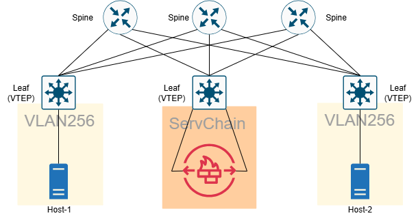
High-Level Topology
1
2
3
4
- Spines: Anycast-RP, PIM-SM
- Leafs: VXLAN VTEPs
- Service-Chain: L2&L3 Traffic Inspector, can be L7 Application service
- Overlay VNIs: 256 (tenant subnets)
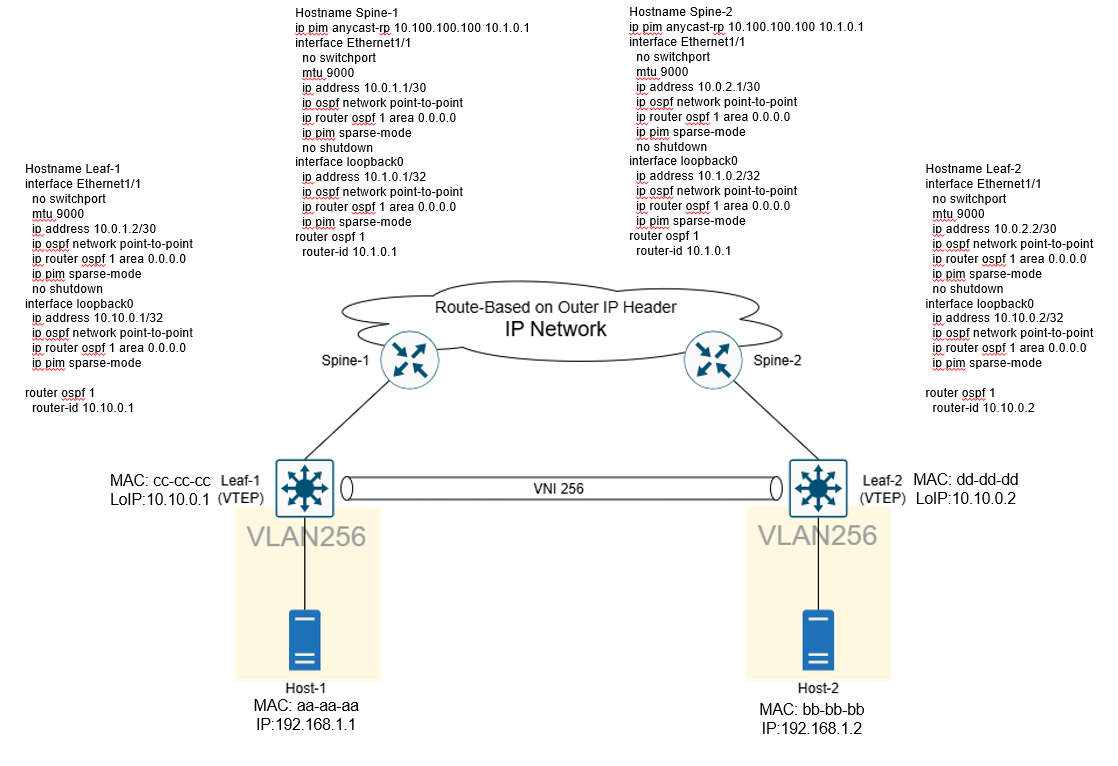
Step 1: Build Underlay Connectivity
Purpose
- Provide IP reachability between all VTEPs (loopback addresses).
- Enable multicast distribution for VXLAN BUM traffic aim for Flood & Learn.
- Deploy Anycast-RP for scalable and redundant multicast rendezvous point in PIM-SM multicast network.
Config Highlights
- Spines configured with
ip pim anycast-rp. - Leafs run OSPF point-to-point with MTU 9000.
- Loopback0 on each device used as VTEP source.
Summary:
- Underlay routing and multicast distribution are ready.
- All VTEPs can now discover each other via loopback addresses.
Step 2: VXLAN Overlay Setup
Purpose
- Map VLANs to VNIs (VXLAN Network Identifiers).
- Establish NVE interfaces with multicast groups for flood-and-learn.
- Extend L2 broadcast domains across the fabric.
Config Highlights
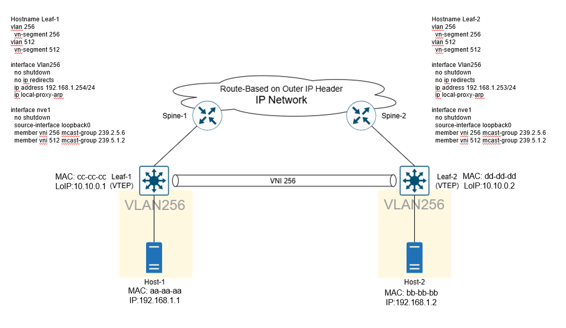
Summary:
- Tenant VLANs (256, 512) mapped to VNIs (256, 512).
- Flood-and-learn mechanism distributes BUM traffic via multicast groups.
- VXLAN tunnels established between Leaf-1 and Leaf-2.
Step 3: Service Chaining with PBR
Purpose
- Redirect traffic through an IPS firewall before forwarding.
- VLAN1000/1001 serve as in/out adjacency to the FortiGate.
- PBR ensures selected traffic is routed via next-hop IPS.
Config Highlights
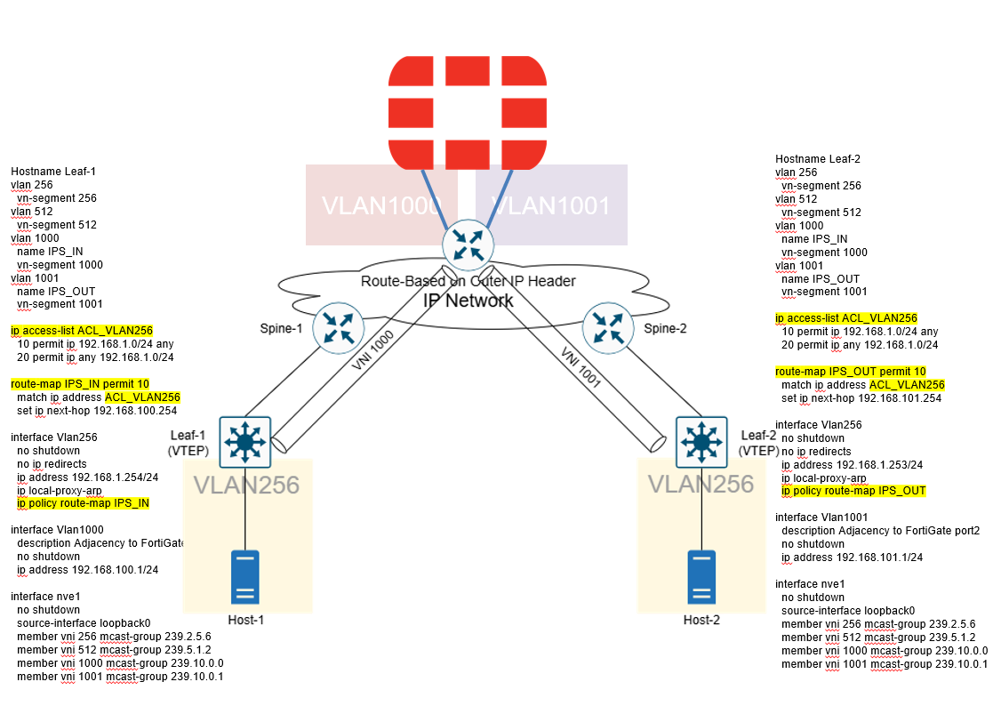
Summary:
- PBR on VLAN256 ensures traffic is intercepted.
- Packets traverse IPS via VLAN1000 → FortiGate → VLAN1001 before reaching destination.
- Service chain successfully established.
Packet Behavior After Implement Service Chain This is the topology. 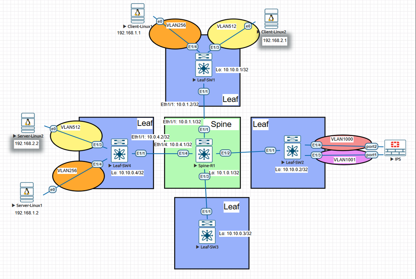
First, Client(192.168.1.1) send out ICMP Ping request 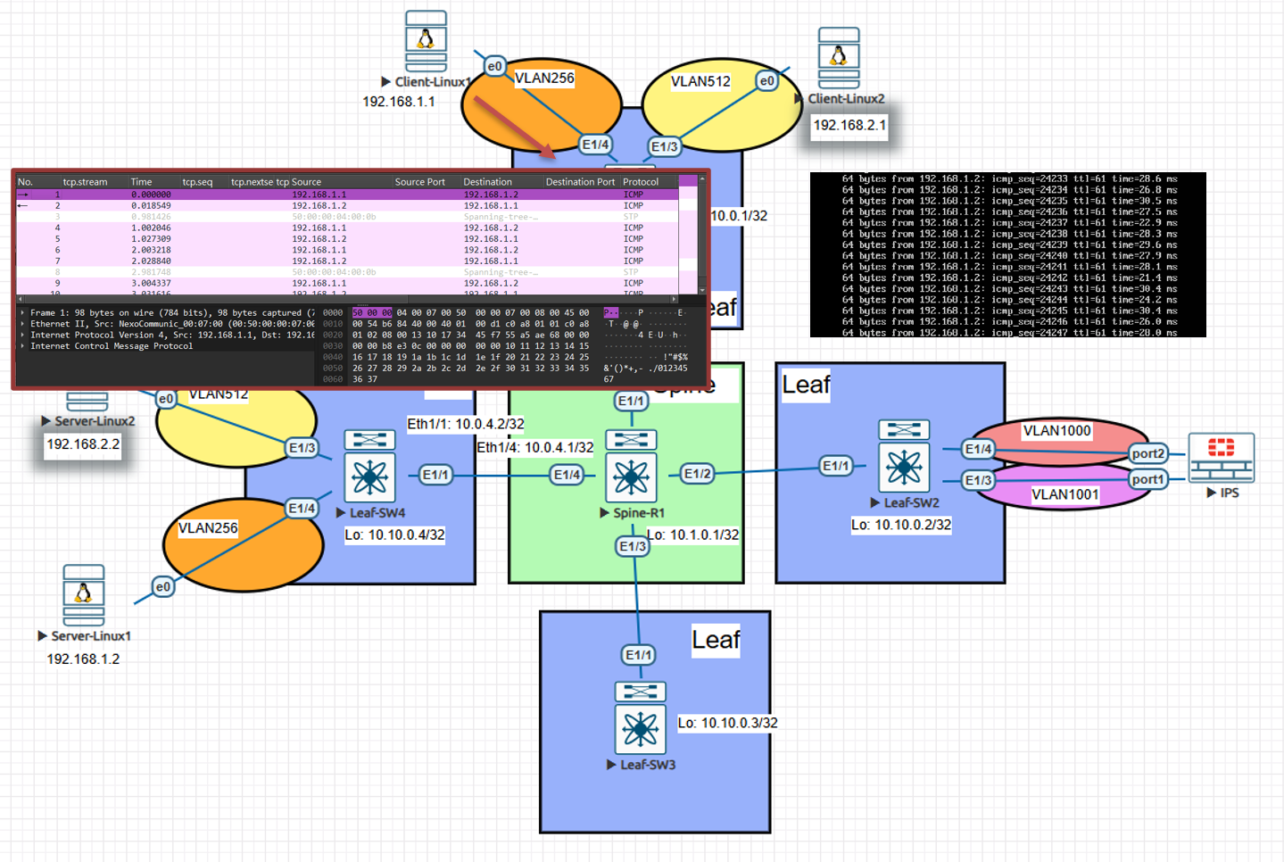 Next, the ICMP packet is forwarded to the VTEP and encapsulated with a VXLAN header around the original ICMP payload. Note the VNID: it is no longer 256 but 1000, because PBR redirected the flow to SVI 1000.
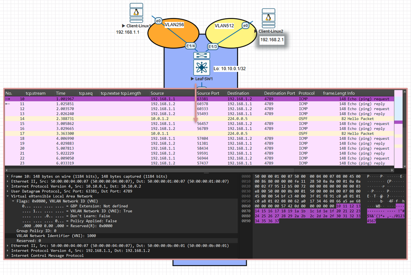
Since the underlay runs OSPF, forwarding is performed using the outer IP header. Once the VXLAN packet reaches the destination VTEP, the VTEP decapsulates the packet and forwards the inner Ethernet frame to the correct destination port based on its MAC table. 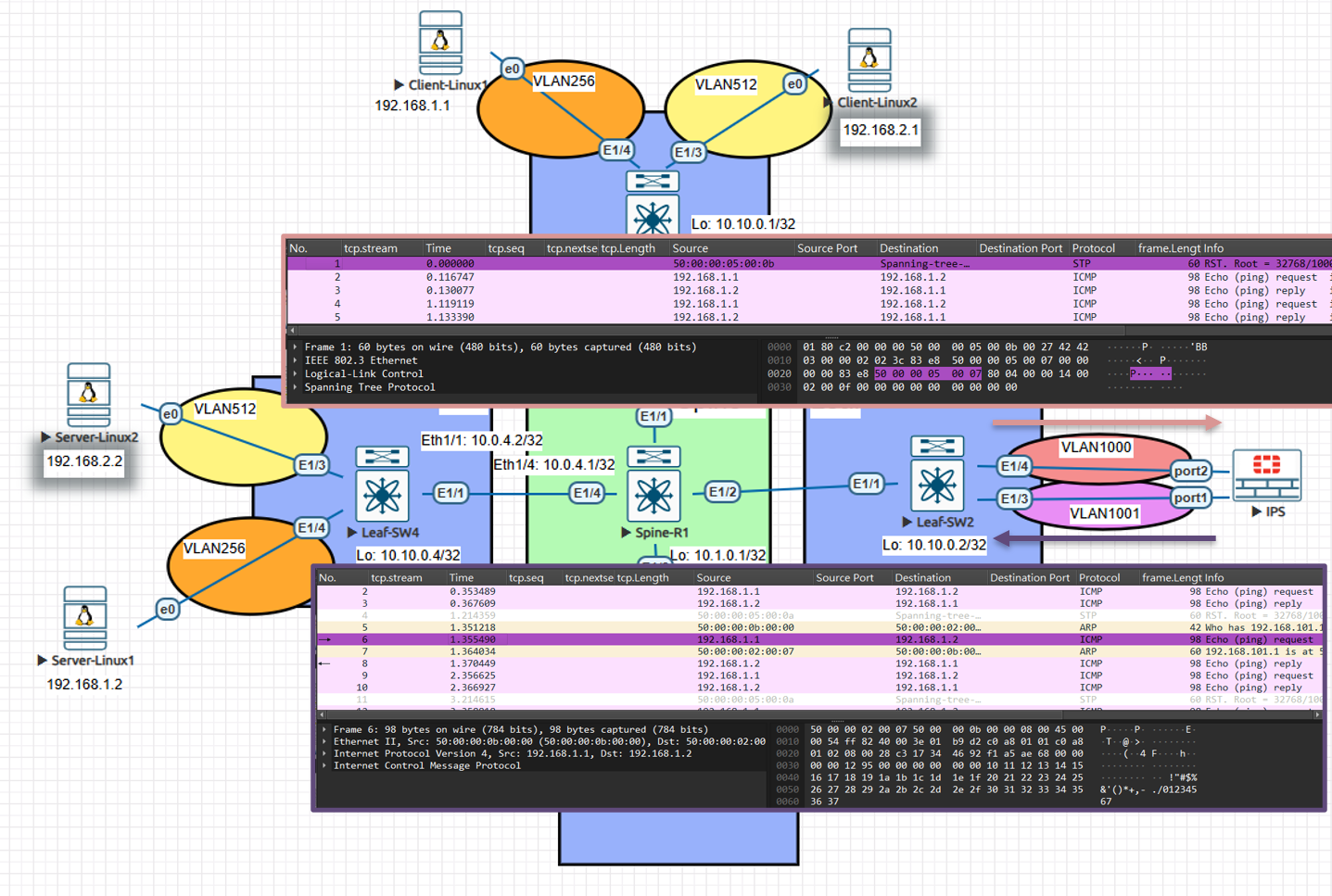
After the service component inspects the traffic, it forwards the packet toward the alternate destination (Server 192.168.1.2). The originating VTEP encapsulates the inner Ethernet frame in a VXLAN tunnel (using the appropriate VNID) and forwards the outer IP packet to the next-hop underlay router, which delivers it to the remote VTEP for decapsulation and final delivery. 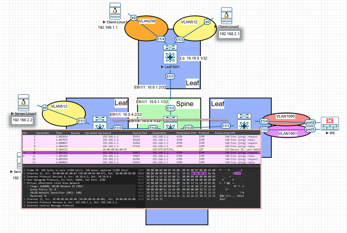 Finally, the VXLAN packet reaches the destination VTEP, which decapsulates the outer headers and forwards the inner Ethernet frame to the endpoint. The ICMP echo request is delivered to 192.168.1.2 and the ping completes successfully.
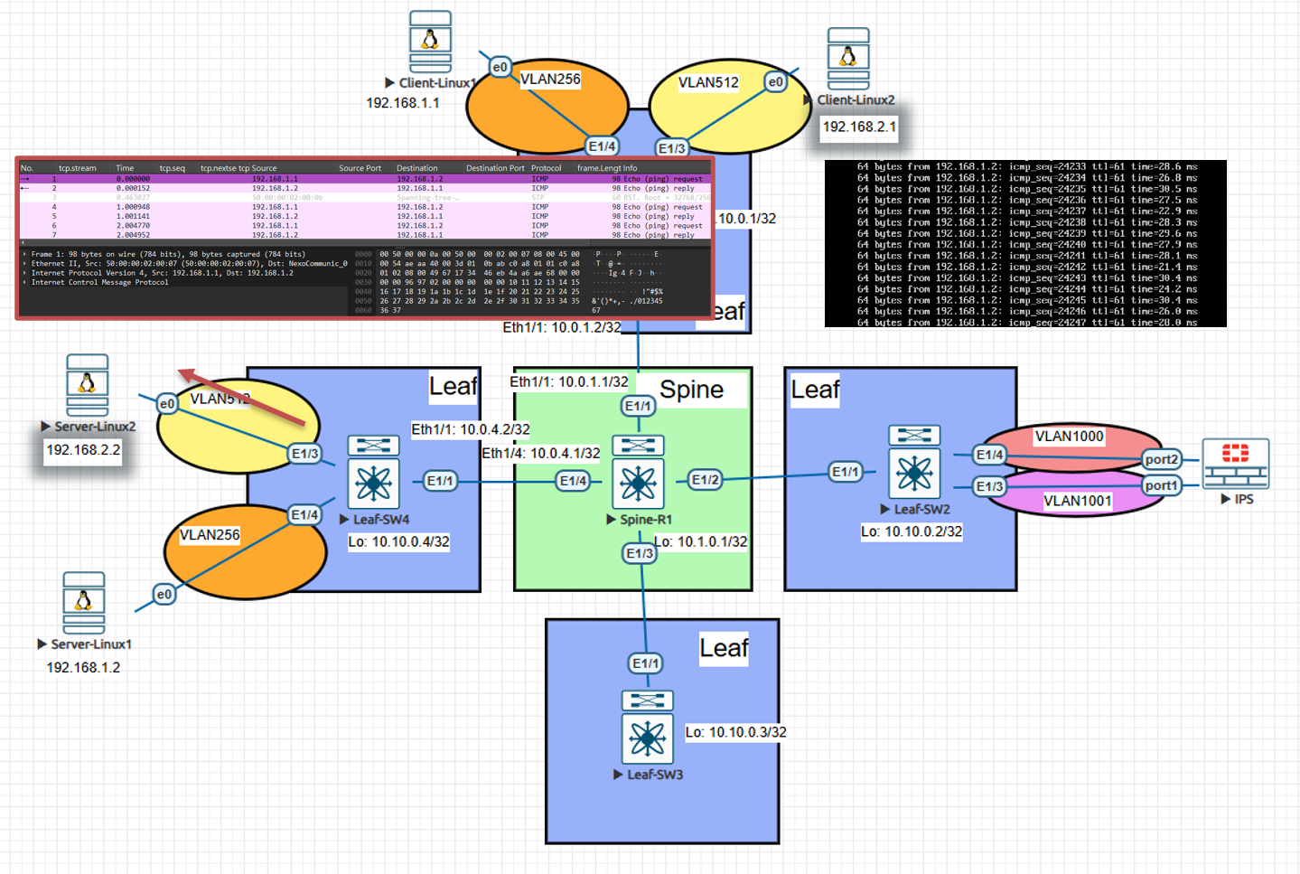
Validation
Suggested Commands
Check NVE peers:
show nve peersCheck VNI mapping:
show vxlan vniCheck PBR counters:
show route-mapEnd-to-end traffic test:
1
2
ping 192.168.1.x
traceroute 192.168.1.x
FortiGate logs: Verify IPS receives traffic from both sides.
Design Considerations
Why Anycast-RP? Provides redundancy for multicast rendezvous across multiple spines.
Why multicast groups per VNI? Ensures BUM traffic for each segment is isolated. Alternative: EVPN control-plane eliminates need for multicast.
Why PBR instead of VRF/service graph? Simpler approach when advanced SDN controllers or ACI aren’t available. PBR can selectively redirect only desired traffic.
Key Takeaways
- Step 1 (Underlay): Built IP reachability and multicast foundation.
- Step 2 (Overlay): VXLAN fabric extended tenant VLANs across Leafs.
- Step 3 (Service Chain): PBR enforced security redirection through IPS.
This architecture shows how legacy Nexus VXLAN flood-and-learn can integrate service chaining without ACI or NSX, leveraging standard features: OSPF, PIM, PBR, and VLAN-to-VNI mappings.
Do you want me to also create diagrams in SVG/PNG that match this document (like topology and packet flow charts), so you can embed them into the Markdown and later into your PPT?